 English
 русский
 Français
 Español
 Português
 عربى

Automotive Foam Part Dimensional Inspection: Methods, Fixtures, and Tolerances
2026-10-30
Content
- 1 Why Automotive Foam Part Dimensional Inspection Needs a Different Baseline than Rigid Parts
- 2 Dimensional Checkpoints and Fixturing for Seat Cushions, Headrests, and Backrest Foam
- 3 Building a Foam Part Dimensional Inspection Control Plan That Scales to Production
- 4 Linking Foam Dimensional Data to Mold Maintenance and Product Development
- 5 Foam Products Released with a Documented Dimensional Baseline
- 6 Foam Dimensional Inspection FAQ
A seat cushion pad measured 1.8 mm from its CAD contour at the supplier was rejected at 4.2 mm during receiving inspection. The material was identical. What changed was the restraint used for measurement. That gap is the real subject of automotive foam part dimensional inspection: it must separate shape error from measurement-condition error.
Unlike stamped steel frames or machined brackets, molded polyurethane parts are not rigid. Dimensional inspection results therefore describe a part state, not an absolute geometry. The accepted state is defined by conditioning time, fixture support, alignment method, and reporting format. Control all four, and the data becomes dependable; miss one, and identical parts produce contradictory readings.
The same pad can report 1.5 mm deviation on a rigid plate, 3.2 mm on a nesting fixture, and 2.4 mm on a vacuum fixture. None of those readings is false. Each describes a different restraint condition. Write the condition into the report before writing the number.
Why Automotive Foam Part Dimensional Inspection Needs a Different Baseline than Rigid Parts
Automotive foam part dimensional inspection must place free-state, restrained-state, and stabilization time into the measurement report, otherwise the same part can produce contradictory results from one shift to the next.
Molded polyurethane foam continues to shrink and recover after demolding. High-resilience seat foam formulations typically stabilize at 72 h under 23 C and 50% relative humidity, and during that window the part can move 1.5-3.5% depending on density, filler content, and geometry. Measuring a cushion at 4 h instead of 72 h changes thickness and contour readings even though the material itself has not failed. The larger problem is compliance. Foam is compressible, probe contact sinks into the skin by 0.2-0.4 mm with a standard ball tip, and unsupported sections of a backrest sag under their own weight.
For that reason, the control plan must name the measurement state before the tolerance. If the OEM contour band is +/-2.5 mm and the insert hole position is +/-0.5 mm, a report without a defined restraint state cannot be audited, reproduced, or used for a production part approval process decision.
Dimensional Checkpoints and Fixturing for Seat Cushions, Headrests, and Backrest Foam
Checkpoints on molded foam parts fall into five groups: form contour, trim lines, hole locations, frame-mating areas, and parting-line flash height.
- Upper contour and side form surfaces control body shape and seating comfort; compare them against CAD with a deviation map rather than single points.
- Trim lines and peripheral edges validate blade-trimmed boundaries that affect cover fit and final seat assembly.
- Hole locations, including headrest rod holes and clip guides, are measured on the mating side where the frame will be inserted.
- Frame-mating areas such as clip slots, wire channels, and fastener recesses must match the steel frame without forced compression.
- Flash height along the mold parting line indicates mold wear early and directly influences hidden surface fit in the finished seat.
The fixture surface should reproduce either the assembly state or the free state. Avoid clamping the pad down to the nominal CAD contour. A rigid backplate with cutouts matching the part geometry, or a vacuum support system with distributed pads, is more reliable. Vacuum pressure should stay below -0.1 bar; higher vacuum pulls the crown area down by 0.5 mm or more and produces a false contour failure.
Useful for hole position, bore patterns, and a small number of audit points. Fast, familiar, repeatable, but sampling density is low and contact pressure sinks into the foam skin. Hard probe compensation is difficult to apply when the surface is compliant.
Captures the full surface in one pass, generates deviation maps, and avoids skin dip. The alignment algorithm must be fixed in advance: best-fit, RPS, or datum reference frame. Changing the alignment strategy can shift contour readings by several millimeters.
Never press the foam toward nominal shape during digitizing. A flexible part measured under forced geometry will pass on the fixture and fail at assembly. A stable grid surface or staged vacuum support is safer than hard clamps.
Building a Foam Part Dimensional Inspection Control Plan That Scales to Production
A production-ready foam dimensional control plan must state conditioning time, restraint setup, alignment method, sample size, and acceptance limits before measurement begins.
A practical starting point for a seat cushion foam core is 2 parts per mold at first-off, 1 part every 4 h during the shift, and a final 72 h stable-state verification on an AQL sample before shipment. Use the same fixture and alignment for all three stages. If the in-process reading drifts in one direction for two consecutive checks, stop, inspect the mold, and review shot weight before releasing more parts.
| Stage | Sampling | Method | Acceptance |
| First-off per mold | 2 parts per tool | 3D scan, 72 h stable state | contour +/-2.5 mm, holes +/-0.5 mm |
| In-process | 1 part every 4 h | 3D scan, free state | no single deviation above 3.0 mm |
| End-of-line | 1 part per shift | touch probe, key holes | holes within +/-0.6 mm, flash visible |
| Shipment | AQL 2.5 | stable state, full contour | compliant to drawing and control plan |
Cycle time decides whether the plan survives on a real production floor. A touch probe routine on contour points, a blue-light scan with fixed alignment, and an inline profiler produce very different inspection costs for the same cushion foam core.
The 72 hour stable-state reading is the contract point for OEM approval. In-process numbers are trend signals that catch tool wear and material drift before they become rejection records.
Linking Foam Dimensional Data to Mold Maintenance and Product Development
Dimensional inspection data should feed mold maintenance and product development, not just end up inside a PPAP folder.
When the same feature repeats the same directional shift across three consecutive batches, for example a seat cushion crown that rises by 0.4 mm per week, the correct response is a mold check, a review of shot weight, and an inspection of parting-line wear. Adjusting process parameters batch by batch masks the root cause and generates constant rework further downstream.
For a supplier that develops molds, runs molded foam, and assembles complete seat systems under one roof, the data loop is short. Zhoushan Jinxin Automobile Parts Co., Ltd., known as JX Seat, connects its foam inspection records directly to maintenance work orders and development and trial run records. This is what makes foam dimensional inspection useful in a supply chain: it becomes a maintenance signal, not only a quality gate.
Repeated 0.3-0.4 mm drift at the same feature across multiple lots is rarely a coincidence. It is a signal from the mold, the foam material, or the restraint condition. Convert that signal into a maintenance work order, and the rejection cost disappears.
Foam Products Released with a Documented Dimensional Baseline
Dimensionally stable foam parts are the ones that enter PPAP, ship to seat assemblers, and survive receiving inspection at an OEM plant without re-measurement conflict.
JX Seat applies this dimensional baseline discipline to its molded seat foam product range. Dual-density polyurethane cushion and backrest cores, plus high-resilience foam cores for ventilated driver seats, are released under the same 72 h stable-state, free-state scan alignment, and mold drift recording routine. Procurement and engineering teams evaluating molded foam suppliers should ask for that documentation before the first pilot run.
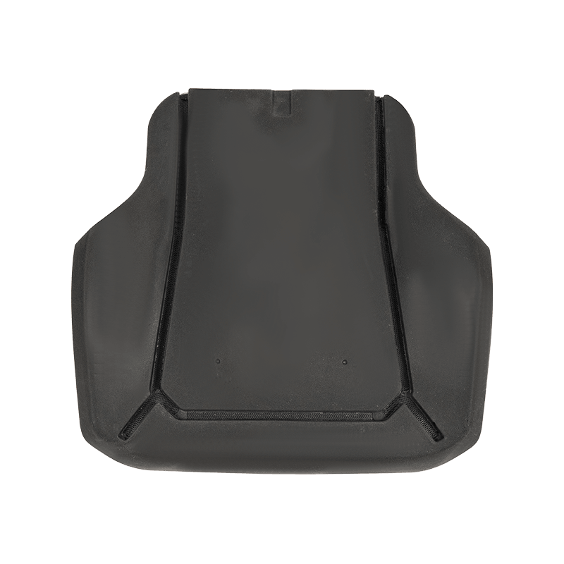
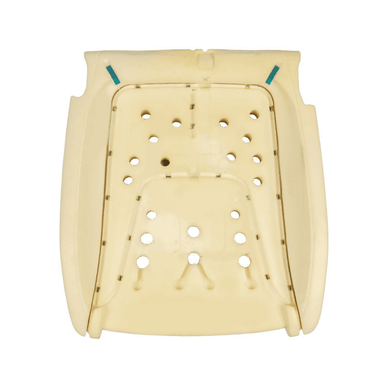
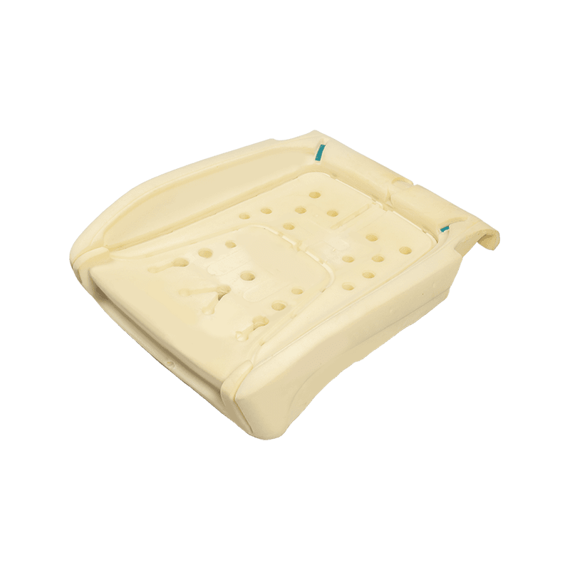 Dual-Density Polyurethane Seat Cushion Foam Core for Front SeatsThis molded cushion foam offers graduated density zones for comfort and support, with ventilation layout and flame-retardant compliance. Its contour and hole positions are critical acceptance features in dimensional checks.View Product →
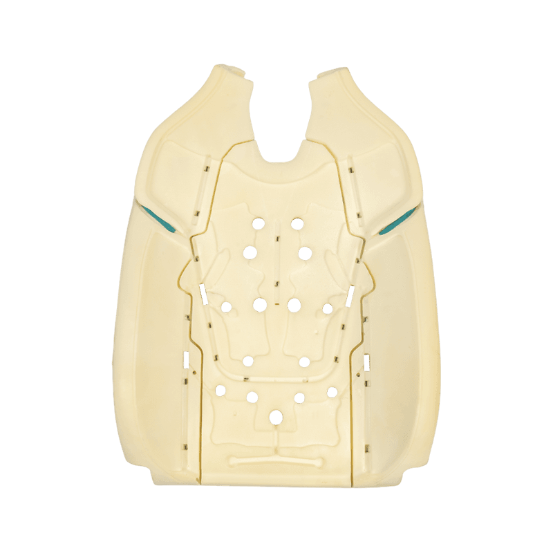
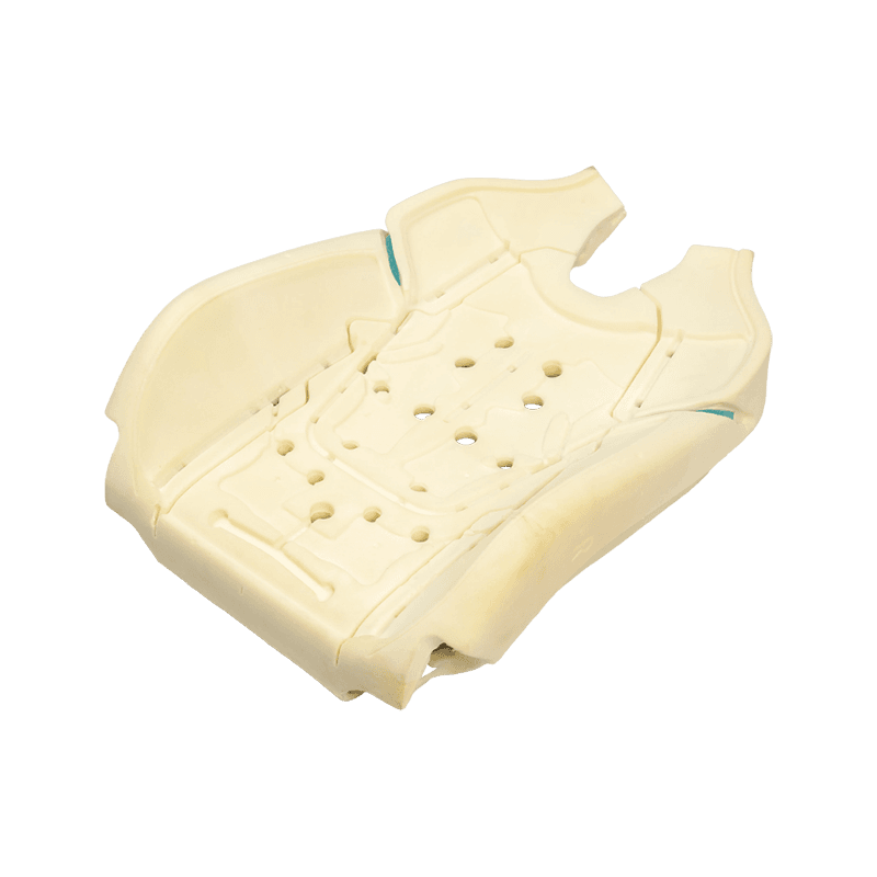 Dual-Density Polyurethane Seat Backrest Foam Core AssemblyThis backrest foam core features soft lumbar and firm side bolsters for spinal support and lateral stability. Its surface contour and trim-line geometry align with the OEM dimensional baseline discussed above.View Product →
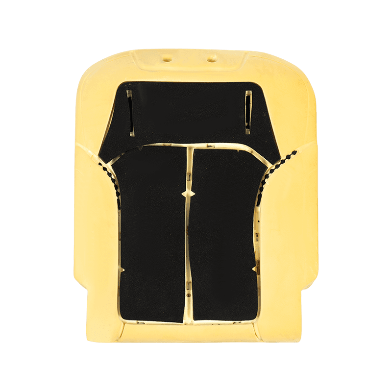
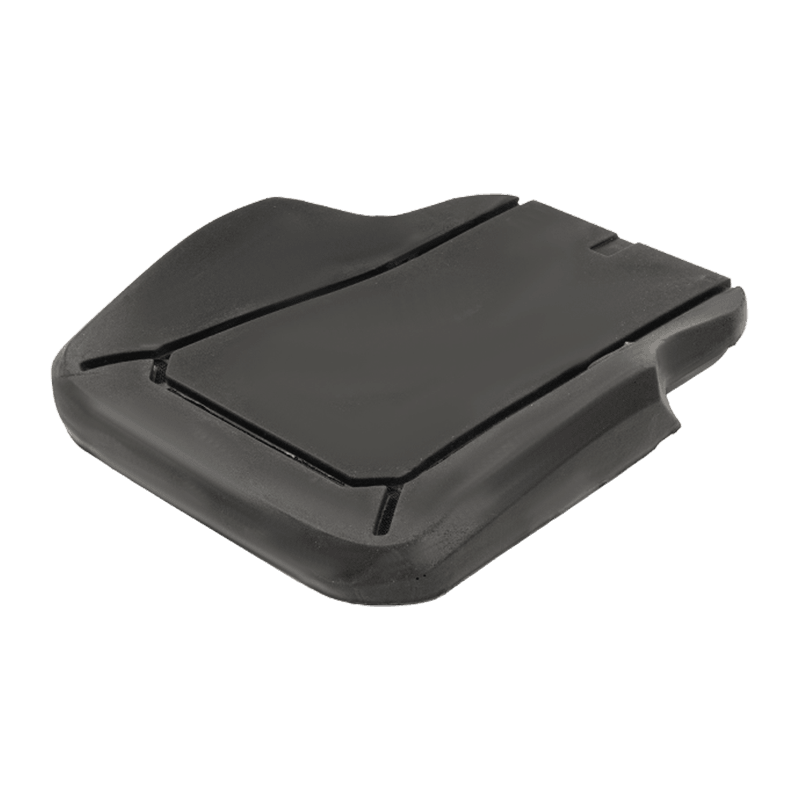 High-Resilience Black Polyurethane Foam Core for Ventilated SeatsThis laminated foam substrate distributes airflow evenly in ventilated seats, with high open-cell porosity and low-VOC additives. Its contour, trim lines, and hole locations are key items in the dimensional acceptance routine.View Product →
Foam Dimensional Inspection FAQ
What does automotive foam part dimensional inspection measure?
It measures surface contour, trim lines, hole locations, frame-mating areas, and parting-line flash height. For a seat cushion foam core, contour and hole position are the two most common acceptance features in an OEM drawing.
Why do polyurethane foam parts change size after demolding?
Molded polyurethane foam continues to shrink and recover after demolding because exothermic reactions cool, gas cells redistribute, and the skin layers relax. Most high-resilience seat foams stabilize near 72 h at 23 C and 50% RH, which is why first-off inspection should use that conditioning point.
What tolerances normally apply to foam seat parts?
Typical budgets are +/-2.5 mm for the main contour and +/-0.5 mm for insert hole position, but the OEM drawing is the only binding source. The important part is that the tolerance is meaningless until the restraint state, conditioning time, and alignment method are recorded.
Should a supplier use a CMM or 3D scanning for foam inspection?
Use a touch probe CMM for hole positions and discrete audit points, and use blue-light 3D scanning for full surface contour. For soft foam, scanning is preferred because it does not compress the skin and it generates a complete deviation map that can be compared against CAD without physical contact.

Copyright © Zhoushan Jinxin Auto Parts Co., Ltd. All Rights Reserved.
Custom OEM Car Seat Frame Assembly Suppliers
